|
|
|
Who's Online
There currently are 6043 guests online. |
|
Categories
|
|
Information
|
|
Featured Product
|
|
|
 |
|
|
There are currently no product reviews.
 ;
Thank you for providing this manual and at low cost.
The Philips scope is of excellent quality, longevity and build and had a couple of faults
when it was passed to me. Having the CCT diagrams is a blessing.
I have fixed the problems and also modded the scope to my requirements.
I have built a 24v Li-Ion pack for portable use from old but good laptop batts.
it is working beautifully and I am well pleased. Keep up the good work Guys.
 ;
manual was very helpful in learning how to propery use my washer. I could not find this manual anywhere else.
;
Awesome quality manual. You really saved my bacon with this one. Was looking for some specific information with regards to my "new" vintage VCR that didn't come with the owners manual. This site is truely a goldmine of available manuals. The quality of the scans are top notch.
Thank-you so much for this awesome manual. If you're looking for this Sony SL-HF400 owners manual, this is the one you NEED to buy. Definitely worth the money.
;
The manual was made available promptly. I is a clean scan of the original. I had no problem downloading it. The scan was well centered and cleanly formatted. It is as good a product as can be had without being the original document.
;
Received downlink in less then 8 hours, Item was in good copy condition, and told me how to program the clock timer. The price was very resonable, and the process was very automated and was GREAT to work with.
INSTALLATION AND SETUP
SETTING THE CROSSOVER(S) Determine your system plans and set the crossover mode switch accordingly. If you plan to use the GTO75.2 or GTO75.4 to drive full-range speakers, set the crossover mode to FLAT and skip to �Setting Input Sensitivity.� Initially set the crossover frequency control midway. While listening to music, adjust the crossover for the least perceived distortion from the speakers, allowing them to reproduce as much bass as possible. Systems using a separate subwoofer set the crossover mode to HP (high pass) for your full-range speakers. Adjust the crossover frequency to limit bass and provide increased system volume with less distortion. For subwoofers, choose the highest frequency that removes vocal information from the sound of the subwoofer. If using the GTO75.2 or GTO75.4 to drive a subwoofer(s), set the crossover mode to LP (low pass). NOTE: The GTO301.1, GTO601.1, GTO1201.1 and the subwoofer output of the GTO755.6 are low-pass only and do not have a crossover mode switch. Figure 12. Control end panel. SETTING INPUT SENSITIVITY 1. Initially turn the INPUT LEVEL control(s) to minimum (counter clockwise). 2. Reconnect the (�) negative lead to the vehicle�s battery. Apply power to the audio system and play a dynamic music track. 3. On the source unit, increase the volume control to 3/4 volume. Slowly increase the INPUT LEVEL control(s) toward three o�clock until you hear slight distortion in the music. Then reduce the INPUT LEVEL slightly until distortion is no longer heard. NOTE: After the source unit is on, red LEDs (on the top panel) will light, indicating the amplifier is on. If not, check the wiring, especially the remote connection from the source unit. Also refer to �Troubleshooting� on the next page. REMOTE LEVEL CONTROL The GTO755.6 and all three GTO subwoofer amplifiers have inputs for an optional remote level control (RLC). This will allow the amplifier�s input level to be adjusted from the listening position. Connect the optional remote level control using the RJ-11 jack on the side of the amplifier. Install the control module in the front of the vehicle within easy reach of the driver. Under the dash or in the center console are both suitable locations. SETTING THE BASS BOOST The GTO755.6, GTO301.1, GTO601.1 and GTO1201.1 are all equipped with a bassboost control. This allows you to adjust the bass output of your system at 50Hz up to 12dB and enhance low frequency. AUX OUTPUT GTO amplifiers (except GTO755.6) are equipped with full-range outputs that can be used to connect additional amplifiers. NOTE: When using the high-level inputs, the AUX outputs can be used to pass a line-level signal to another amplifier. INSTALLING NEON TUBES (OPTIONAL) 1. Using a Phillips screwdriver, remove all screws on the amplifier�s output/power end panel and set them aside. 2. Using a 3 �32-inch Allen wrench, remove only the screws on the amplifier�s (top) clear cover and set them aside. 3. Remove the end panel and slide the cover off. Set both parts aside. 4. Locate the enclosed hardware bag and remove the four clips. Each clip has a square end and a larger round end. Using a round end, press two clips onto each neon tube (e.g., Street Glow AN9 or equivalent), as shown in Figure 13. 5. For each tube, align both clips so the square ends slide onto an exposed extrusion edge, as shown in Figure 9. Do not cover any screw holes. When installed correctly, each neon tube will sit under an extrusion and not be visible when viewed from directly above. 6. Route each neon tube�s power cable through its respective NEON hole on the end panel (see Figure 13). 7. Slide the cover back into place and reinstall its screws. Then, replace the end panel and reinstall its screws. 8. Finish the installation of the neon tubes as instructed in their owner�s manual.
GTO75.2
GTO75.4
GTOB300.1/600.1/1200.1
GTO75.6
6
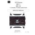 $4.99 GTO301.1 JBL
Service Manual Complete service manual in digital format (PDF File). Service manuals usually contains circuit diagr…
|
|
|
> |
|