|
|
|
Who's Online
There currently are 5942 guests and
1 member online. |
|
Categories
|
|
Information
|
|
Featured Product
|
|
|
 |
|
|
There are currently no product reviews.
 ;
A great copy of the manual, and the only one I could find anywhere on the net! The circuit diagrams are easily readable, all component values marked and easy to see. A highly appreciated download!
 ;
Great Manual. This manual is available no where else. It was exactly what I was looking for.
;
The TEAC A-1500's Service Manual was instrumental in reviving this classic reel-to-reel. Not only does it have the schematics, exploded parts diagram and parts list, it also provided mechanical adjustment information that approximate factory default settings.
;
This service manual was determinant to enable to fix my Alpine Amplifier. I am pleased with my purchase. For a 5 star rating I would like to see a higher resolution scan of the printed circuit board lay-out because the gray scale grafics was dificult to see. Also some schematic diagrams were scanned at a slight angle. Never the less, it had all information I needed to troubleshoot and service my equipment.
;
Complete manual, the good quality of reproduction allows enlarged print-out of the schematic diagram in the size it probably had in the original print edition and which is necessary for practical use.
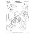
Amplifier/Subwoofer
SUB125
CONTROLS AND THEIR FUNCTION
1 2 3 4
SPEAKER LEVEL OUTPUT L C R
SPEAKER LEVEL INPUT L C R
ON
LINE LEVEL
INPUT
AUTO
SUBWOOFER LEVEL
L R
MIN MAX
5
SUB125
6
STAND BY
POWER
ON
7 8
AC 120V~,60Hz 160W
FUSE 2A/250V FUSE
9
1. Speaker Level Outputs - Connect the Left, Center and Right speakers to these connectors. 2. Speaker Level Inputs - These High Level Inputs are for receivers that do not have line-level �pre-amp out� or �subwoofer out� jacks. When a pair of main or satellite speakers are attached to the OUTPUT terminals, they are driven the full range of frequencies as generated by the music source (receiver, amplifier, etc.) 3. Line Level Input - These left and right Line Level Inputs are normally used when the receiver/ processor has line-level �pre-amp out � or �subwoofer out� jacks. 4. Auto/On Switch - This switch allows you to set the Mode of the Amplifier. Turn the switch to Auto to cause it to Auto-matically turn on when it receives a signal and Auto-matically turn off after twenty minutes without a signal. If this switch is left �On�, the subwoofer will always be ON when the power switch is turned On, regardless of input signal.
5. Subwoofer Level - This knob controls the volume level of the SUB125. 6. LED - Red & Green. The LEDs indicate the Mode status that the subwoofer is in. When the SUB125 is turned OFF neither LED will be lit. The Green LED will light when the SUB125 is ON and receiving a signal. The Red LED will light when the amplifier has not received a signal for twenty minutes. The subwoofer will turn on when your receiver/amplifier begins playing again. 7. Power Switch - This the master power switch. Use it (in Off mode) to disconnect power to the amplifier. 8. Fuse - Use only same type of fuses. For the U.S. 120V version use only a 2A 250V fuse. For the European 230V version use only a 1A fuse. 9. AC Cord
5
|
|
|
> |
|